EdgeBond: Thermoplastic Bonding for Microfluidics with Minimal Feature Distortion and Lid Sagging

The lidding of plastic microfluidic devices remains one of the biggest hurdles to realize their promise of sophisticated but inexpensive disposables for diagnostics, research, and life science applications. The holy grail remains sealing devices using matched materials, without significant collapse or deformation of the features, and without introducing any foreign materials such as adhesives or solvent.
Introducing EdgeBond, a new lamination method for lidding microfluidic devices and other thermoplastic parts, available only from Edge Precision Manufacturing. EdgeBond is a thermal bonding technique that offers the strength, integrity, material compatibility, and all other traditional advantages of high-heat thermal bonding, without the associated disadvantages of deformation, sagging, and dimensional variation commonly experienced when using this and other bonding techniques.
EdgeBond permits microfluidic geometries in thermoplastic parts which would be difficult or even impossible using other lamination techniques. These include high aspect ratio chambers that could not previously be sealed without prohibitive lid sagging and delicate features which would otherwise suffer unacceptable deformation. Moreover, EdgeBond improves dimensional tolerance in finished parts and minimizes part-to-part variation. That means biological and chemical assays function as designed, reliably and reproducibly.
Background
Like other plastic parts, microfluidic devices made from thermoplastics may be joined and lidded by adhesive, solvent, or thermal bonding techniques. However, lidding with adhesives is likely to harm any biological material used on the chip, and may be incompatible with other reagents—especially solvents, which can delaminate an adhesive lid. Solvent bonding weakens the bond area, causes feature deformation, and can result in residual solvent leaching into the interior space of the part, raising its own issues of biological and chemical compatibility.
For these reasons, thermal bonding is often the preferred method for lidding microfluidic parts. Lidding by thermal bonding produces a device with uniform composition, which in turn simplifies downstream surface chemistry, reduces issues related to refraction, and minimizes the possibility of supply chain issues. As the thermoplastic materials used for microfluidic systems have high biological and chemical compatibility, and thermal bonding introduces no foreign material, thermal bonding typically eliminates these concerns in terms of part manufacture.
Thermal bonding, however, comes with its own set of drawbacks.
Because lidding by thermal bond involves applying pressure to the parts and heating them to near or even above their glass transition temperature, some degree of deformation is unavoidable. A compromise temperature and pressure must therefore be found that produces a sufficiently strong bond while keeping feature deformation within acceptable tolerances. In macroscopic applications involving the permanent joining of thermoplastic parts, such as consumer goods and food packaging, the range of acceptable temperature and pressure is wide, because small deformations in the joined area will generally not affect the function of the part. Delicate adjustments to temperature and pressure are only necessary at this large dimensional scale, in applications that require reversible seals, such as the thermally bonded film covers used to seal many plastic containers.
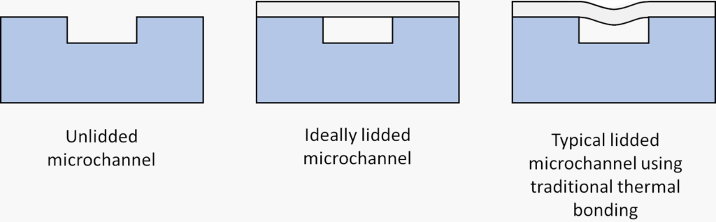
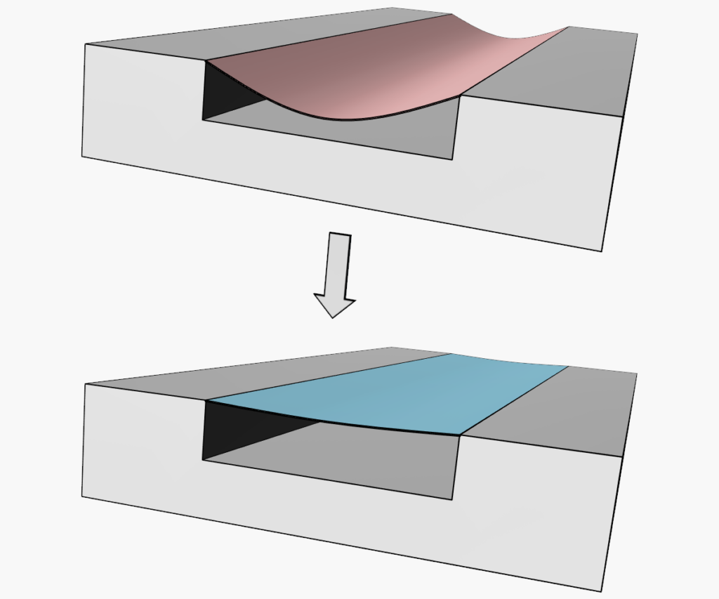
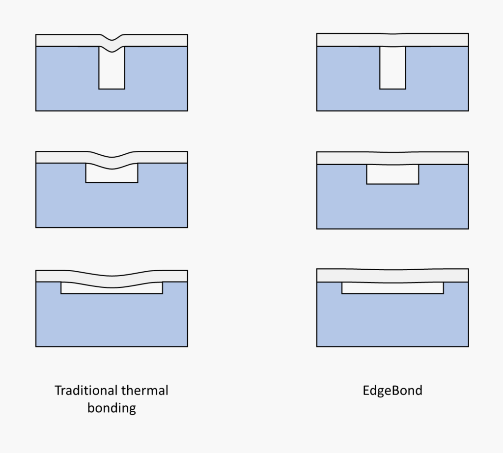
Deformation is a common issue in bonding for applications of microfluidics, however, where geometric precision is critical to a thermoplastic part’s proper function. Lids and smaller features, unsurprisingly, begin to experience deformation at lower temperatures and pressures than larger features. With traditional thermal bonding techniques, this results in lid sagging, a condition in which the lid intrudes into channels, chambers, and other negative spaces of the device. Deformations of mere microns, which are trivial to macroscopic assemblies, can be a significant detriment in microfluidic chips. Deformations of tens of microns—still just a rounding error in most manufacturing applications—can make the difference between a functional and nonfunctional microfluidic device.
Lid sagging can be particularly problematic for features with a high aspect ratio of width to depth. Lid sagging constricts the geometry of the feature, potentially pushing it outside acceptable tolerances. In extreme cases, a sagged lid can become bonded to the lower surface of a channel or chamber, creating a bifurcated or completely collapsed feature where none was intended. In all cases, lid sagging constricts the feature and increases fluid resistance.
These effects may cause unwanted issues in any microfluidic application, but will be particularly problematic in those involving flow cytometry, light manipulation of cells, and cell applications generally. Sagging will also change shear stress profiles, hydrodynamic properties, and pressure drops along channel lengths. Non-fluidic features can also be negatively affected by lid sagging if, for example, a transparent lid makes contact with or disrupts the geometry of optical waveguides. If the application involves detecting and characterizing cells or other material attached to the lid, sagging produces a non-flat surface which is incompatible with optical hardware with a narrow focal plane.
Features on the base side of the device may also be distorted by thermal bonding. Thinner and more delicate features, such as pillars or narrow walls on the order of ten micrometers in width, are particularly prone to becoming squashed or slanted when lidded by thermal bonding.
Even larger features are not immune to distortion. The edges of large features may become rounded under excess heat, and their vertical faces may bulge. This can result in distorted walls that intrude into channels or slant to one side. This disrupts channel geometry and, in extreme cases, may seal off the channel entirely.
All of these issues can be reduced by lowering the temperature and pressure of bonding, but this compromise will reduce bond strength. Lessened bond strength, in turn, lowers the durability of the device, limits maximum internal pressure, reduces robustness to variance in the manufacturing process, and potentially increases the rate at which devices fail QC testing.
If the compromise conditions are too narrow, variable effects across the bonded area can push local bonding conditions outside of the acceptable range—typically too high in the center, and/or too low at the edges. In such cases, an acceptable compromise between bond integrity and dimensional tolerance may simply not exist within the part as designed, and the microfluidic application will have to be abandoned or the device redesigned to accommodate the vagaries of the thermal bonding process.
Taken together, these issues place severe constraints on the design of microfluidic parts, complicate the manufacturing process, and make some applications flat-out impossible.
The EdgeBond Difference
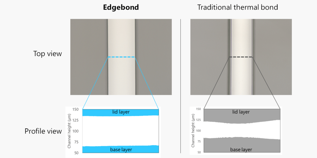
EdgeBond features all the advantages of traditional thermal bonding. Base and lid material are matched, and the process involves no adhesives, solvents, or foreign materials of any kind. This results in minimum refraction at the joint, with maximum chemical and biological compatibility.
A proprietary fixture design minimizes, and in some cases nearly completely eliminates, lid sagging and feature deformation during the bonding process. Channels and chambers with width-to-height ratios of 10:1 or higher can be produced to excellent tolerance, even when employing a very thin lid for maximum optical clarity. In concert with Edge’s soft compression molding technology, which permits pillar and wall features with high aspect ratios and zero draft angle, traditional microfluidic design constraints are lifted, allowing a wider range of aspect ratios than previously possible.
Even devices that are currently lidded using traditional techniques can be made better with EdgeBond, which improves feature edge sharpness, surface flatness, and wall straightness. By keeping the finished dimensions of channels and other features close to their designed values, EdgeBond produces a part to the best possible tolerance. Particularly in applications which require precise flow modeling and optical features, this can mean the difference between a device that requires endless iterations, and a device that works as expected, from prototype to manufacture.
Additionally, EdgeBond produces more uniform bonding geometry and quality, both across a single device and from part to part. Uniformity is critical to reproducibility, making EdgeBond invaluable for microfluidic lab-on-a-chip applications that need to minimize sample or reagent volume.
Taken together, these advantages make EdgeBond the perfect substitute for solvent and traditional thermal bonding in all applications, and for adhesive bonding in applications where film delamination by solvent or leaching of adhesive material is a potential issue. It is the ideal bonding technique for parts that require tight tolerances, geometric fidelity, and true-to-model functional performance in finished devices.
EdgeBond is available only from Edge Precision Manufacturing, and can be ordered for bonding applications in all thermoplastic parts, from prototypes and research-grade devices to high-quality manufactured products.